Phase Progression
The steps we took to success.
Phase Structure
The ATLAS was developed through a four step iterative process, from an initial sketch model to a machined and (literally) polished final product. This process is aligned with the sprint structure of Olin College of Engineering’s Principles of Integrated Engineering course and reflects our team’s desire to pursue an adaptable iterative design rather than committing to a single high-risk build.
Phase One
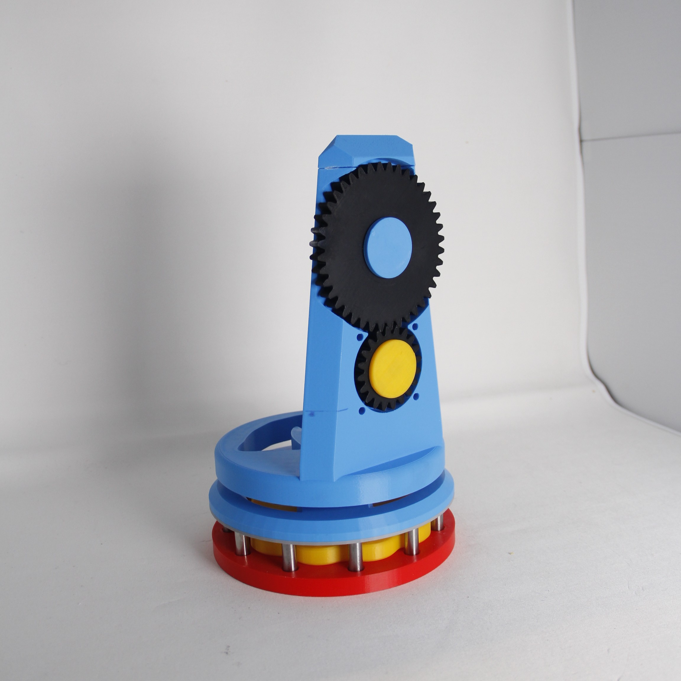
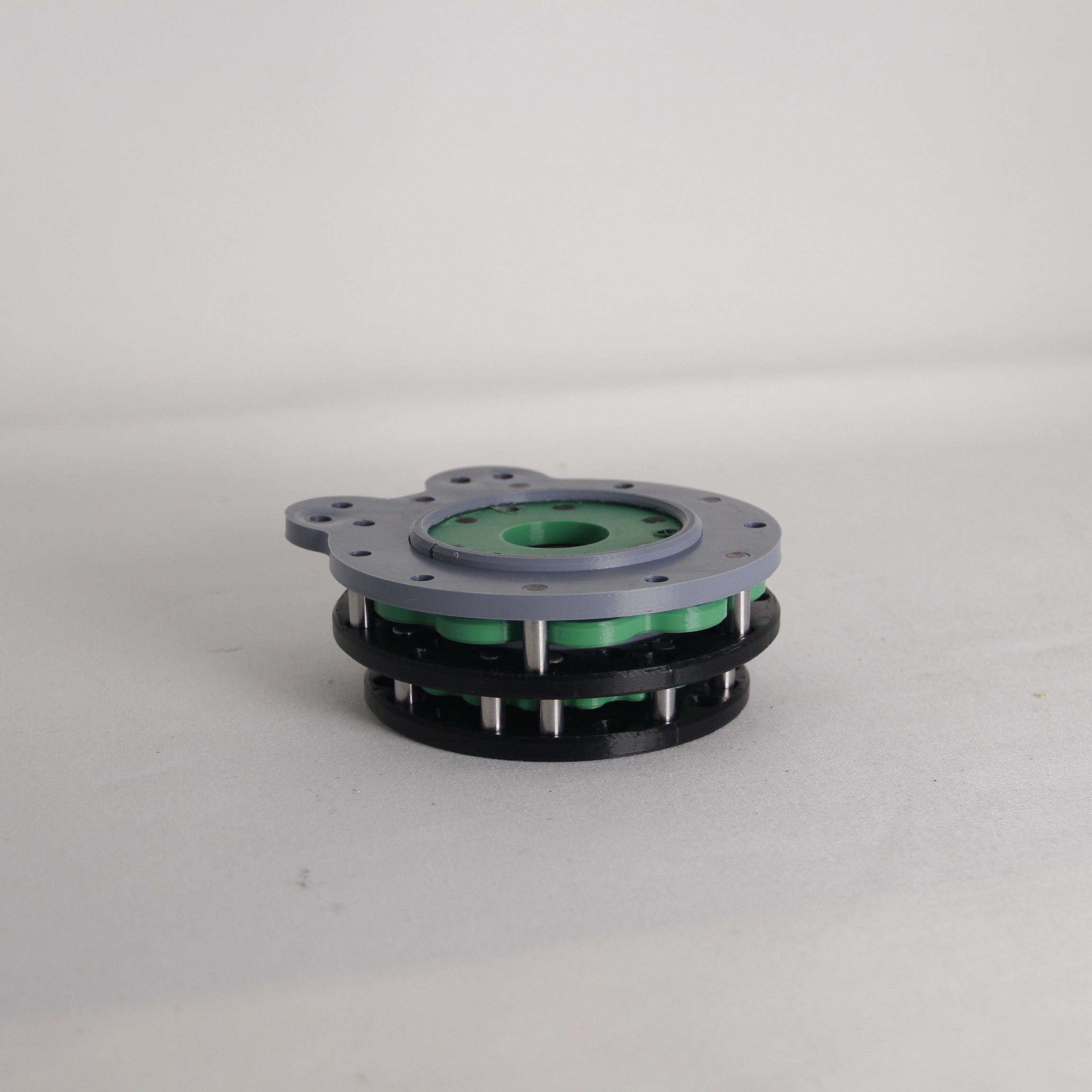
The initial design iteration consisted of a simple, 3D-printed prototype of a single stage cyclodial drive, driven by a servo motor. We selected a cycloidal drive because it offers exceptionally smooth motion, and its inherently high gear ratio made it well suited for precise tracking. While this version did not include a camera mounting mechanism, it demonstrated that the cycloidal drive design functioned appropriately and provided sufficient confidence to proceed through to the next iteration without a significant investment in time or materials.
Computationally, Phase 1 focused heavily on the development of the software needed for ATLAS to locate and track a stellar object. This was done by way of a Plate-Solving algorithm, which compares asterisms on a reference image populated with astronomical objects to other images from various astronomical databases in order to determine where the center of the reference image is located in the Equatorial coordinate plane. Due to our initial plate-solving algorithm being extremely unoptimized thanks to the many requests we had to send back and forth, we decided to take advantage of the Astrometry database’s resources to consolidate our algorithm. Thanks to this, we merely need to provide an appropriate image and query for the returned coordinates—the asterism cross-referencing is done autonomously. hen ATLAS’ coordinates have been determined, the user can request to track any of the twenty million astronomical objects within the SIMBAD database, at which point the ATLAS Telescope will move to the specified location. Once on target, ATLAS will continually move at a speed of 0.25 degrees/minute to keep in alignment with Earth’s sidereal time.
Phase Two
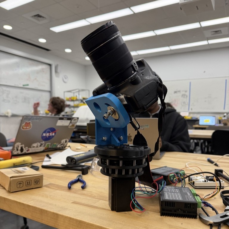
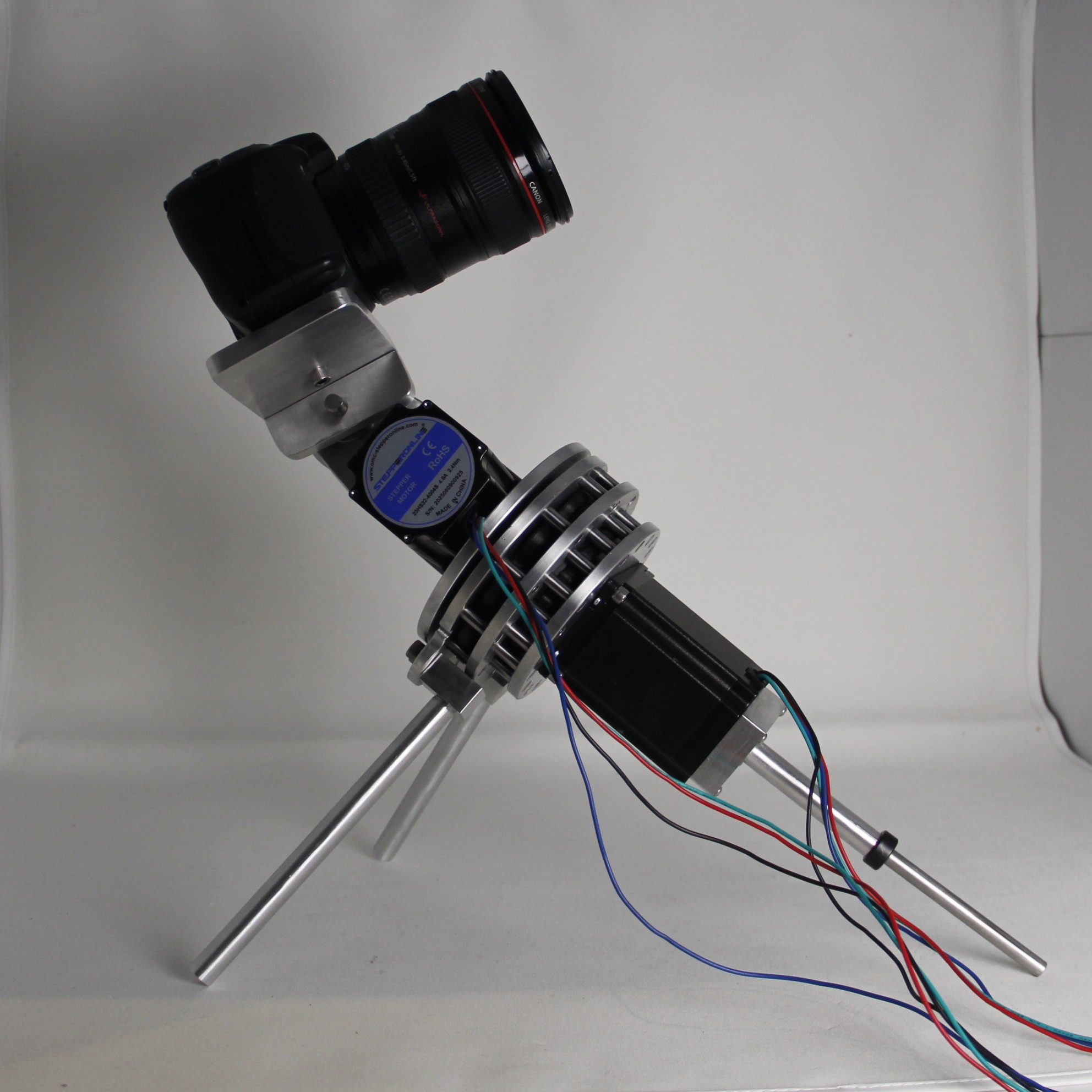
During this sprint, the Polar Alignment System (PAS) was integrated into ATLAS. The PAS converts ATLAS from an altazimuth to an equatorial mount through a three-leg system attached directly to the cycloidal drive housing with an adjustable front-leg to allow for elevation adjustments from 30-45 degrees. The adjustable equatorial mount allows the camera's polar axis to be aligned with Earth’s rotational axis, simplifying star tracking by reducing the required degrees of motion while tracking. Once aligned, tracking can be completed primarily through the use of a single axis, driven by the cycloidal drive, which improves accuracy and efficiency. Additionally, this mount style allows us to use a smaller reduction rate of 5:1 on the declination axis. This allows the telescope to adjust to a target astronomical object and minimizes the need for high-precision stepping during tracking.
Both motors were powered by two, separate AC adapters and controlled by discrete signals sent from the Raspberry Pi using the RPi.GPIO library. Testing revealed that stalling of the motors and inaccurate timing resulted from the use of the Linux OS system. The second design iteration also outlined the implementation of the programmatic control of a camera, so as to allow ATLAS to calibrate itself and capture photos of the stars without human intervention. This required the use of the gphoto2 library, which we chose due to its modularity and (relatively) detailed documentation. Through the library, we were able to fully automate the photo-taking process. We also created a variety of “modes”, or specific configurations of the camera’s settings built to optimize the photography of specific astronomical objects. We encountered a variety of issues while trying to integrate this into our workflow, particularly with the gphoto2 error “[-110: I/O In Progress]”. Through rigorous debugging, we were able to determine that the issue arose from the camera’s shutter speed, which shaped how we handled setting optimization going forward.
Phase Three
The third iteration focused heavily on design for manufacturing. This involved slimming down wall thicknesses to better mimic metal stock and redesigning most components so they could be produced on the mill or lathe. This phase revealed several key issues, particularly with camera orientation and the tolerancing of the cycloidal drive, which informed changes for the final design. Throughout the third phase, the brunt of the software changes came from optimizing the movement of the two NEMA-23 motors. We pivoted to the pigpio library which utilizes Daemon software to send PWM signals to the motors for precise timing by handling direct hardware communication. Our telescope now moves along one “axis” at a time.
Phase Four
The final iteration was the most challenging. From a machining standpoint, the team had varying levels of experience, which required us to adapt, communicate clearly, and work closely together to complete the parts. These components also needed to integrate seamlessly with the electrical system; if tolerances were incorrect, we would have needed to pivot back to a fully 3D-printed final version. While we encountered a few machining mishaps, donated stock allowed us to machine the majority of the star tracker and complete the final assembly. Limit switches were also added to prevent the camera from colliding with the tilt motor mounted directly below it. The star tracking algorithm was also iterated upon, improving its success rate by capturing RAW images as opposed to JPEGs, before converting them into FITS files for cleaner processing. More preset capture modes were added and validated with real-life testing, where we compiled long-exposure images of ( Betelgeuse ) and ( Rigel ).
Along with these changes, more preset capture modes were added and validated with real-life testing, where we used 10-second exposures coupled with an ISO of 400 to compile long-exposure images of Cassiopeia and the Cat’s Eye Nebula.