Mechanical, Electrical, and Software Design
The build behind the beauty.
High-Level Design & Tradeoffs
Project Scale
Our initial goal was to design a portable star tracker that could be transported and deployed by a single person in areas with little to no light pollution. We intentionally avoided a large, stationary system that would need to remain in one location or require multiple people to move. A smaller footprint also reduced manufacturing risk, which was important since this was the first machining experience for some members of the team.
Materials & Aesthetics
One of our primary goals was to produce a machined final iteration to expand our machining skills and present a more professional-level final product. At the same time, our design allows for a completely 3D-printed build, which we tested extensively during earlier iterations. This choice makes the system more accessible, as amateur astronomers can print the parts themselves and assemble their own version. For the machined version, we chose 6061 aluminum because it is easy to source, forgiving to machine, and stiff enough to prevent flex in the camera arm and drive housing, which improves long-exposure image stability.
Design Tradeoffs
- Printed vs. Machined Components: We kept the geometry printable during early development so new astronomers could replicate the system without tooling. The final version used machined 6061 aluminum where rigidity directly improves consistency and thus image quality.
- Equatorial vs. Alt-Az Alignment: An equatorial mount lets us track on a single axis once aligned to Earth’s pole. This reduced the control problem and eliminated constant two-axis motion.
- Cycloidal Reduction vs. Planetary or Worm Gears: Cycloidal drives produce high ratios with smooth motion and tolerate printed tolerances. A worm gear would stall smaller steppers and microstepping would be too jittery.
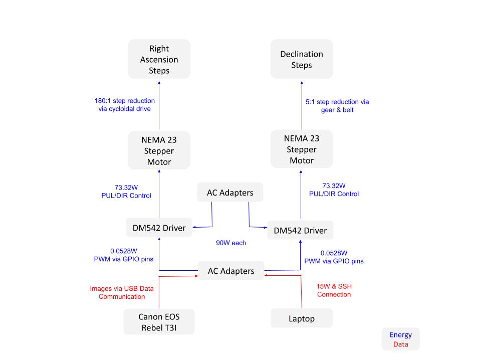
- NEMA-23 Steppers Instead of Smaller Motors: Smaller motors stalled during slow micro stepping. NEMA-23s provided enough torque margin to avoid missed steps at 0.025deg/min additionally their size and density made them integrate well into the final design as structural components.
- Software Timing vs. Hardware Timing: The original GPIO control suffered from Linux jitter. Switching to pigpio and daemon-driven pulses fixed the timing problem and prevented step loss.
- Standalone Camera Control vs. Manual Shooting: Automating capture through gphoto2 reduced user error and allowed raw astrophotography presets instead of adjusting exposure by hand.
- One-Axis Tracking vs. Two-Axis Control: By aligning the RA axis mechanically, we avoided writing a continuous two-axis correction loop. That made tracking simpler and more reliable.
- Portability vs. Size/Stiffness: A small system is easier to backpack into dark fields but offers less mechanical rigidity. We accepted that trade-off and reinforced the final metal version where needed.
- Low-Cost Replication vs. Maximum Rigidity: The BOM keeps a fully printed option viable for under $250 while still supporting a higher-rigidity aluminum build for users with access to a mill.
Initial Design Organization
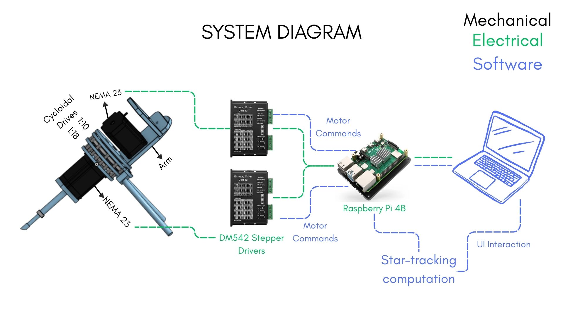
Mechanical Design
A link to the Starglazers OnShape can be found here.
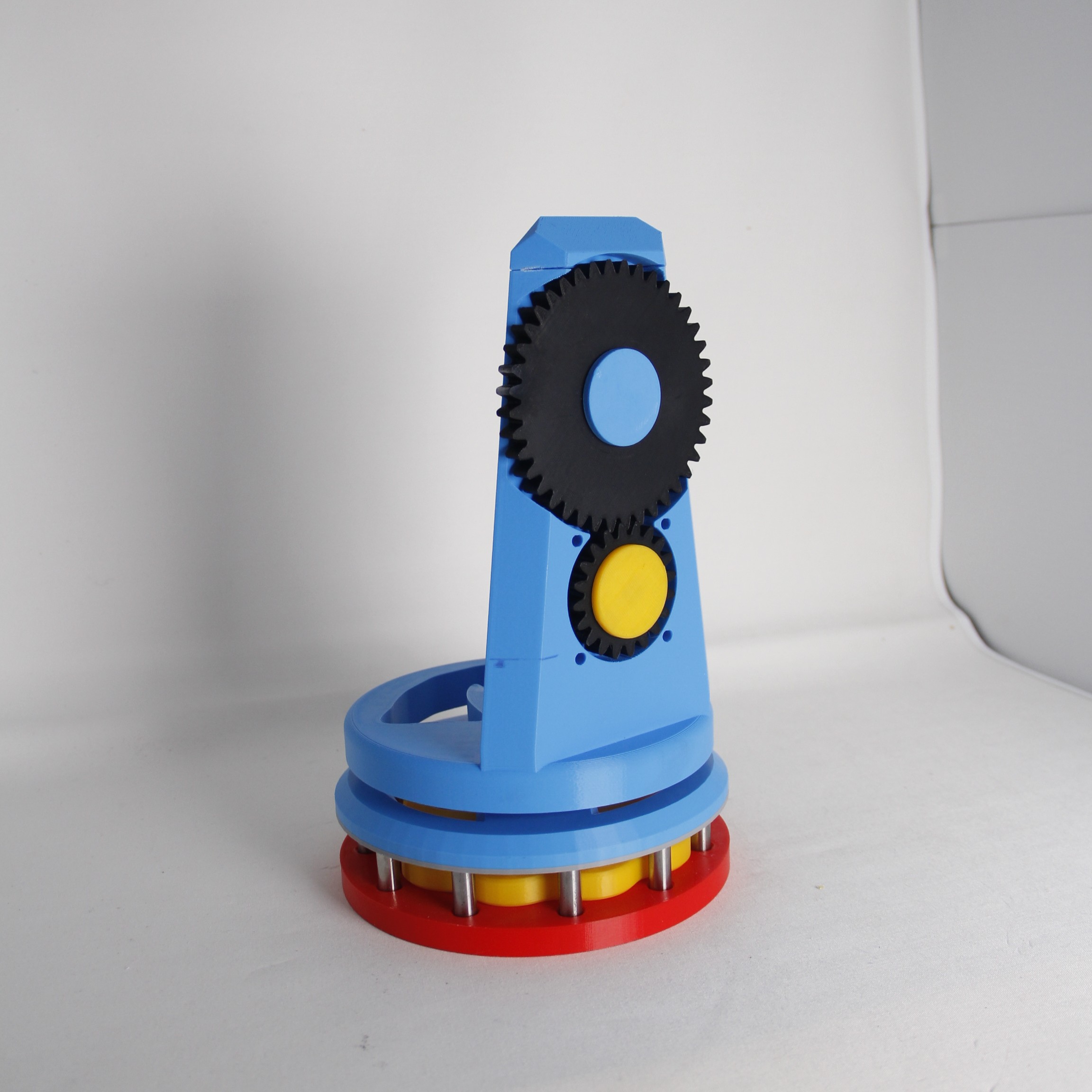
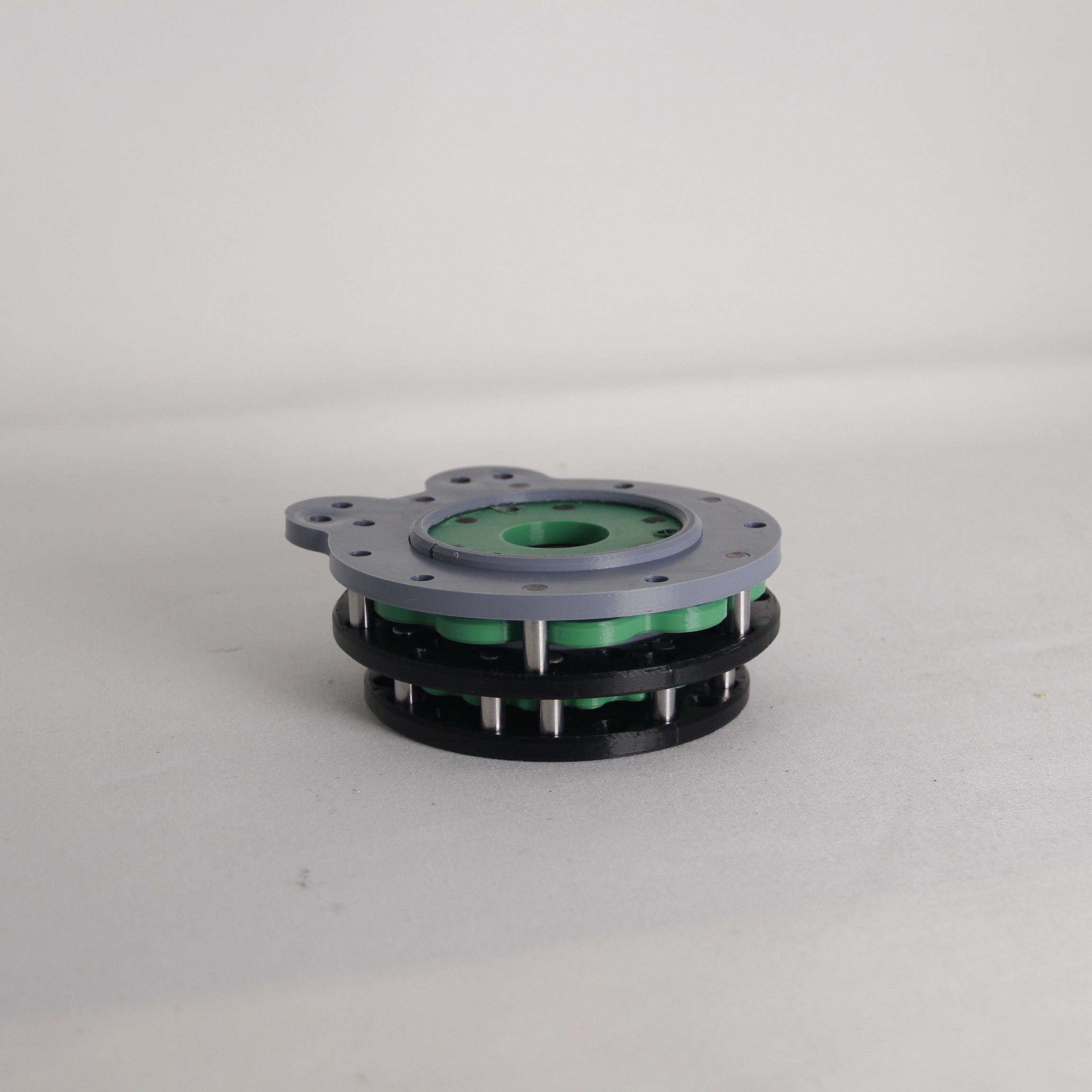
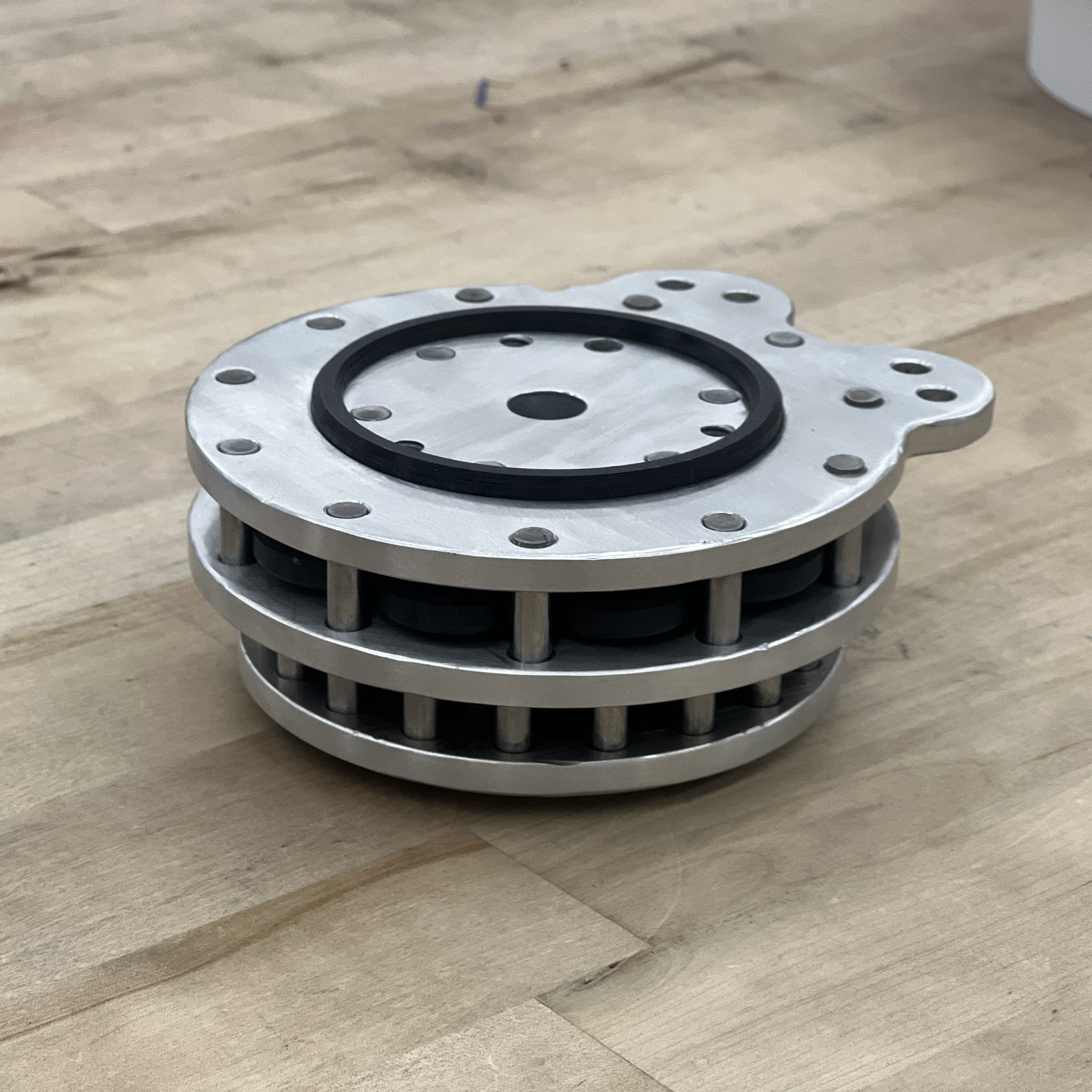
Cycloidal Drive
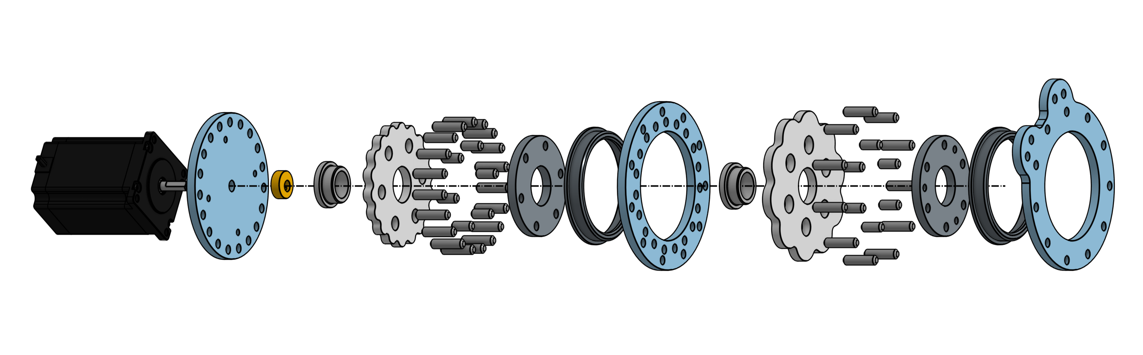
In order to smoothly track the stars, it’s crucial to be able to make miniscule movements at an extremely slow rate. The way we chose to accomplish this is through the use of a Cycloidal Drive: An unconventional type of ‘gearbox’ that can provide gear reductions inline with a shaft, at extremely high precision and with very small amounts of backlash if designed properly. The drive works by turning a flower-shaped ‘gear’ eccentrically, causing it to walk around, meshing with an outer circle of pins, and turning an internal ring of pins. There is conventionally one more pin than there are lobes, which creates a gear ratio of 1:# lobes.
For our purposes, we took into account a number of factors. First, the earth rotates at a rate of 0.025 degrees per minute. Secondly, our stepper motors operate at a rate of 200 steps/revolution, and we want to utilize full steps rather than micro-stepping for full accuracy. Finally, we need to follow the rotation of the earth very closely, to ensure that the star we’re interested in stays perfectly centered for long exposure photography. These factors ultimately led us to choose a 180:1 gear reduction, which gives us a rotation rate of 0.01 degrees per step on the stepper motor. This resolution ultimately provided us excellent results.
We chose to accomplish this ratio through a two-stage reduction. By using a 10:1 drive, inline with an 18:1, we could achieve extremely accurate results without too much additional mechanical complexity.
The entire assembly is made from stacked 1/4inch plates, sandwiching the cycloids in between, using press-fit pins as fasteners. While this ultimately wasn’t the best choice in terms of ease of assembly with the tools we have available, it was relatively straightforward and created a beautiful finished product. Instead of bearings, due to the compact nature of the assembly, we were forced to use low-friction bushings that combine thrust and radial support. Due to the low speeds/wear this assembly undergoes, this proved to be a perfectly reasonable choice.
For machining, we chose to design the entire structure to be manufactured out 1/4inch 6061 plate aluminum. We were able to source this easily, and it allowed us to be flexible in our machining strategy. While we initially intended to waterjet these parts and post-process them afterwards, we milled the major components on a fixture plate for simplicity and accuracy.
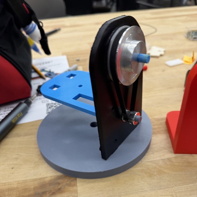
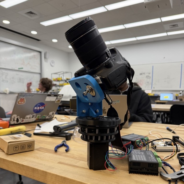
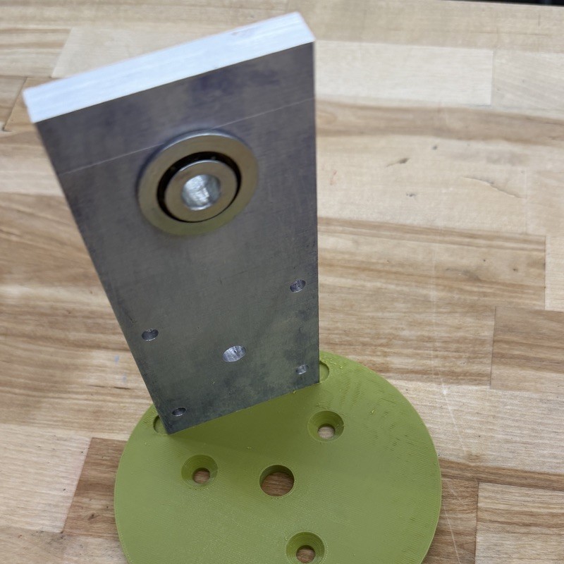
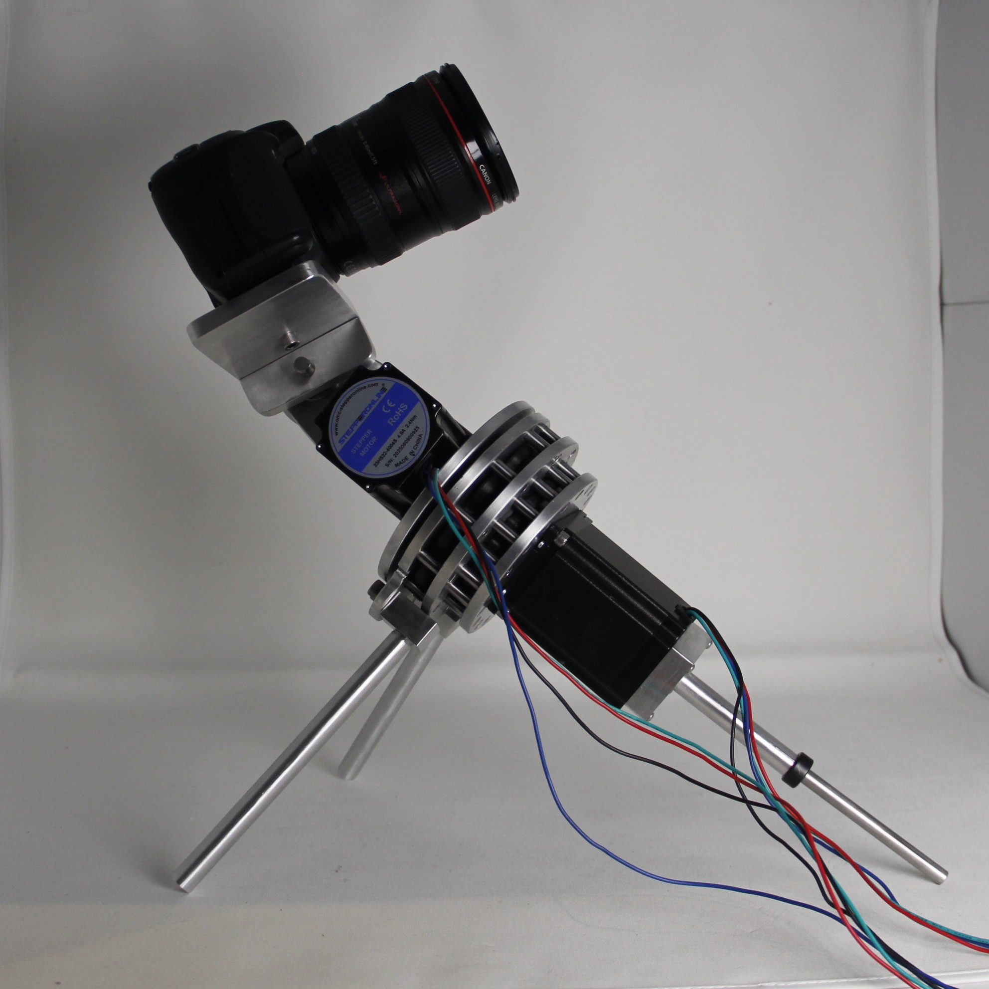
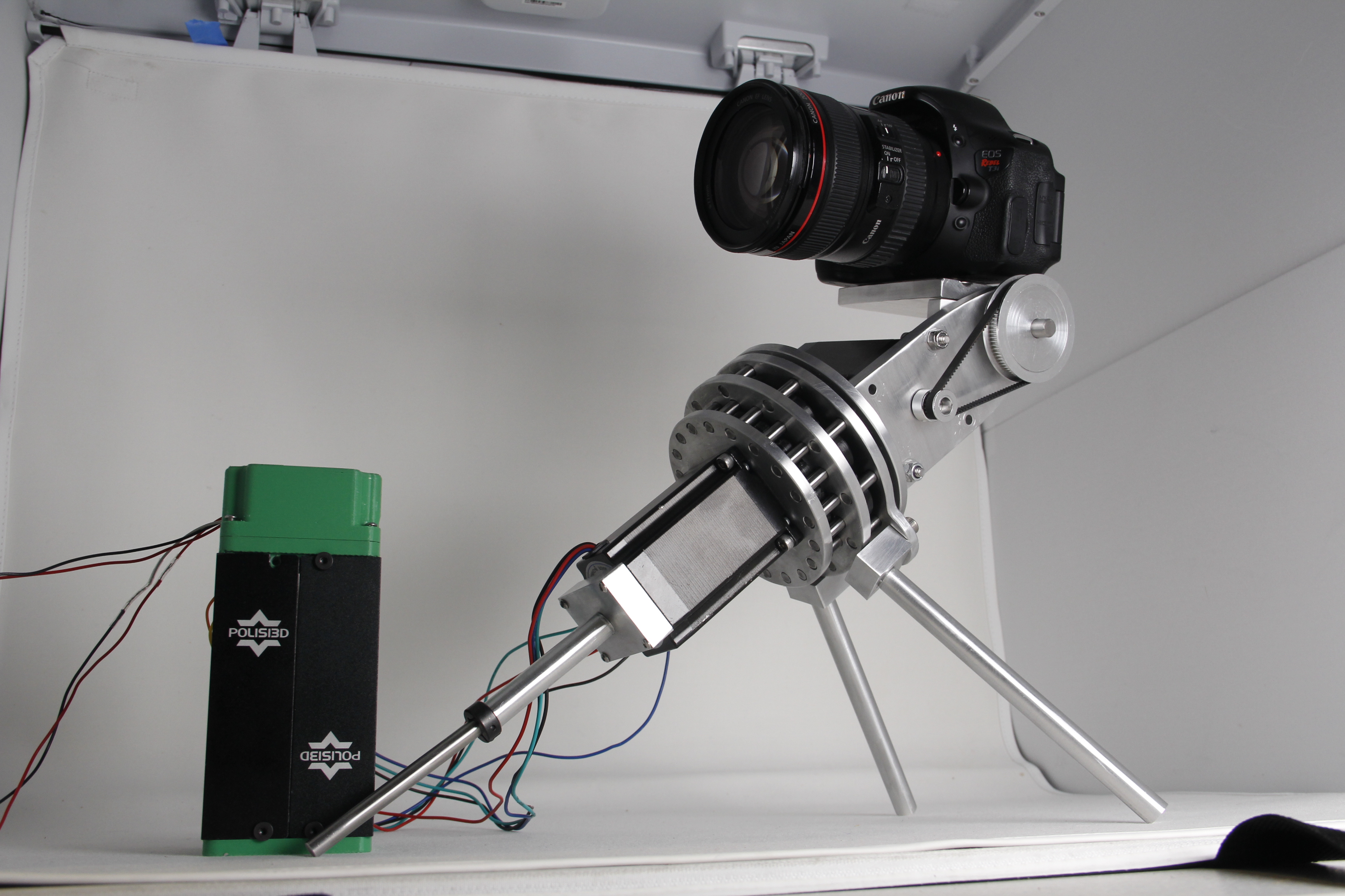
Camera Arm & Mount

The arm and camera mount are made up of several main components. The base plate attaches directly to the cycloidal drive and includes a slot for the vertical arm. This vertical arm houses the motor as well as the gear reduction, and it supports a steel pin and bearing that connect to the camera mount. The choice to use a steel shaft was important. In early iterations, we tested a 3D-printed shaft, but it experienced noticeable torsional deformation due to the combined torque from the camera weight and the gear reduction. Switching to steel significantly improved stiffness and reduced twisting under load.
A standard off-the-shelf bearing was added to reduce friction between the pin and the arm, allowing smoother rotation and reducing wear on the components. The arm plate and camera mount plate were made from 3/8 inch 6061 aluminum, which provided more strength than strictly necessary but helped ensure rigidity. This thickness was also practical because the material was available as leftover scrap stock, allowing us to avoid purchasing additional material. The base plate for the arm was made from 1/4 inch 6061 aluminum, which matched other structural components in the system and was also readily available as extra stock. Using materials we already had on hand helped reduce cost while keeping the overall structure stiff and reliable.
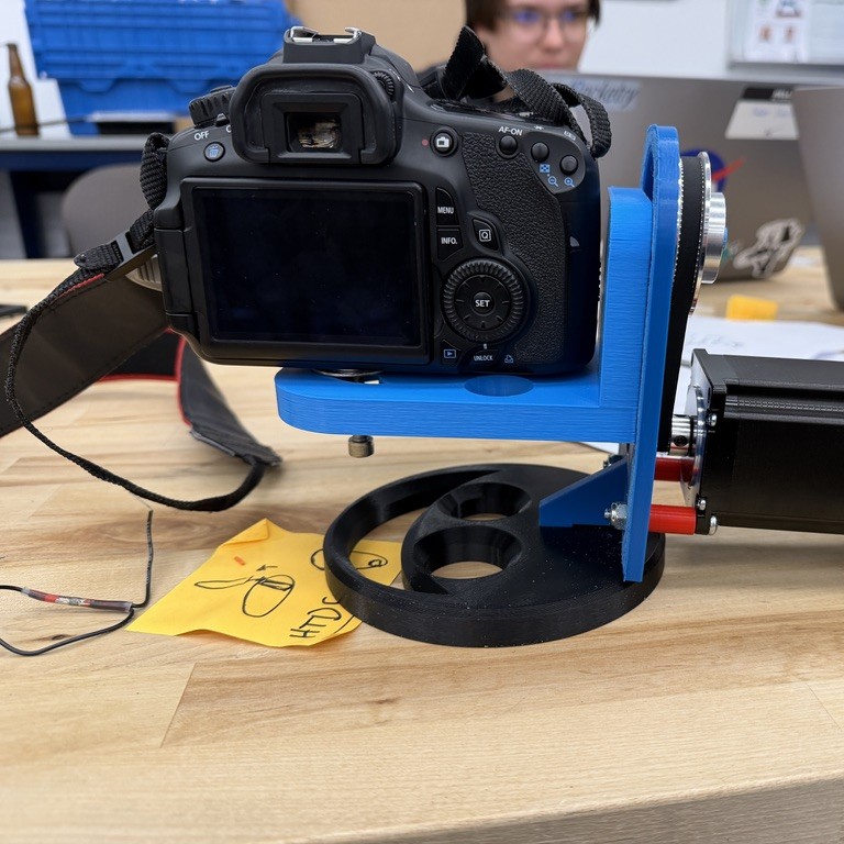
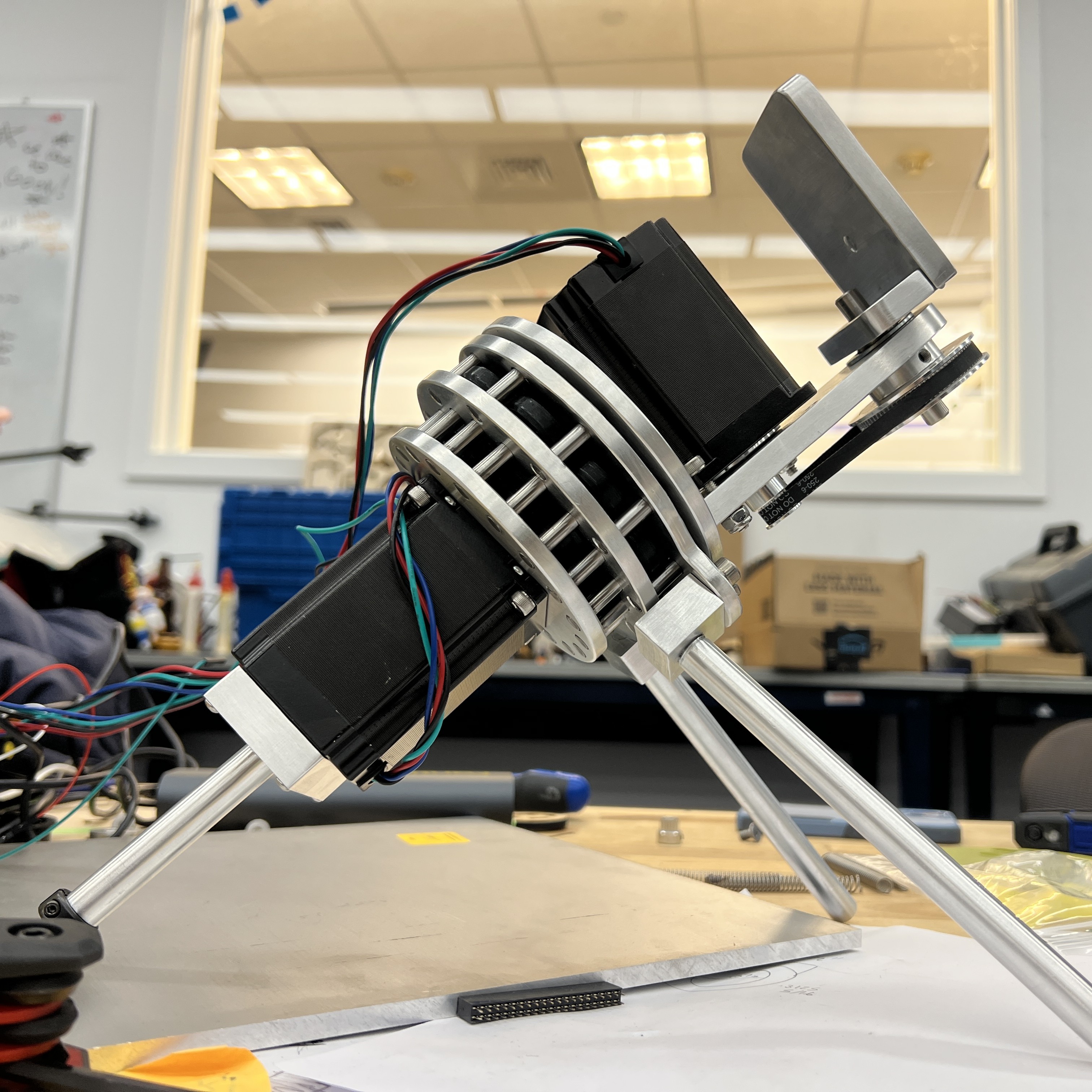
Polar Alignment System
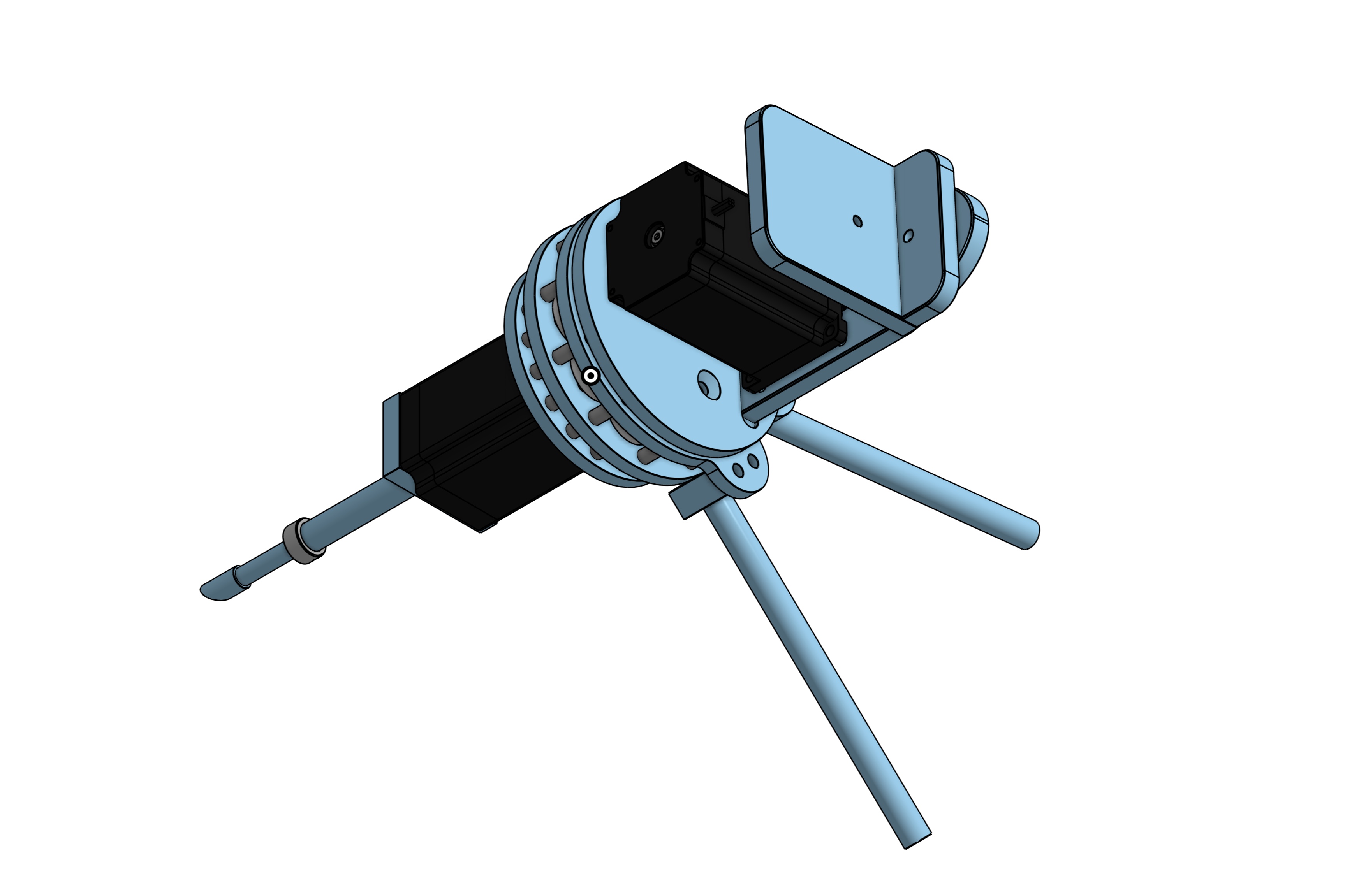
Early in the design process, we chose to pursue an equatorial mount rather than an alt-azimuth mount in order to achieve smoother tracking and better image quality. In an equatorial system, once the right ascension axis is aligned with Earth’s rotation, the system only needs to rotate about a single axis to track a star. This simplifies control compared to an alt-azimuth mount, where both motors must move continuously to follow the same object.
The Polar Alignment System allows ATLAS to be converted into an equatorial style telescope. In order to achieve an equatorial mount system that could support the weight of the cycloidal drive and mount without interfering with the mechanisms, we decided to use a three leg system. Using MATLAB, calculations were performed to find the optimal attachment locations to support the weight of the mount and to find optimal leg lengths provided stock limitations and allow for inclination adjustability.
In order to increase functionality and adaptability, the front leg features an adjustable element that allows the angle of inclination to range from 30-45 degrees. This works through a hollow shaft that another shaft fits into. The inner-shaft can be adjusted to change the front leg length and locked into place using a shaft collar. The adjustable leg is attached to the bottom of the cycloidal drive motor using a custom attachment part. The two back legs are secured through attachment blocks that are secured to the top plate of the cycloidal drive housing. Additionally, all legs are able to be removed by simply unscrewing the legs from the attachment mounts to convert the telescope to an altazimuth.